11+ Wiring Diagram Ats
Get the Right Fix Right Now. 01 07.

Automatic Transferred Switch Ats Circuit Diagram Electrical Engineering Blog Transfer Switch Circuit Diagram Electrical Circuit Diagram
ATS safely switches sources or loads and enables the shutdown and isolation.

. Hooked up see wiring diagram. When looking at the wiring diagram take some time to. Web By Philip Marcelo Associated Press.
Web The ATS-03 module not only has a built in 11-second flasher but it also is a Load Equalizer which allows you to use small incandescent bulbs. Identifix Wiring Diagram For. Web An ATS wiring diagram is a schematic representation of the component connections and its function.
Typical systems have sensing. 4 will send a signal to cell phones nationwide. Web The wiring diagram is shown on the left and 2P3P4P ATS main part wiring is shown from top to bottom.
An emergency broadcast system test on Oct. Web UL US 5 YEAR UL1008 LISTED WARRANTY APPLICATION The Model LUT-ATS-D is a single zone silent emergency transfer control with universal dimming capability. Type 225AF 2.
6 ATS With SW1 CB1 On Unit is in. ATS UPS Fig 2. When selecting an ATS panel for a.
Web Common symbols used on ATS diagrams include wires switches resistors capacitors and inductors. Web This video shows ATS automatic transfer switch changeover wiring diagram. 11 ATS Specification and Classification.
Other specific matters needing attention are as follows. Web Figure 2 depicts a power system with the backup source generator powering loads through a three-pole ATS solid neutral with ground-fault present. Go back to the Contents Table.
The wiring diagram shows the power source control. Web Safety 2 Automatic Transfer Switch Owners Manual Keep the transfer switch enclosure door closed and bolted at all times. See Figure 3 for load shed.
Web 11 General The Eaton load shed provides four 4 sets of contacts that can be used to control connected loads on the generator Source 2. Ad Vehicle Wiring Diagrams for 98 of All Makes and Models. For 98 of All Makes and Models.
Correct mounting method A B C above are correct A is. Only qualified personnel should be permitted access. Web WIRING DIAGRAM Fig 1.
Typical Single-Phase ATS Transfer Mechanism Utility Service Circuit Breaker if equipped The utility service circuit breakers for 200 amp models are. Web Figure 1 ATS Panels with contactor as a switching mechanism. Web 05162023 113000 Title.
ATS GTS LINE OUT Doc 020-161-B0 Rev. GTS FXM FAMILY FXM FAMILY Fig 3. Automatic transfer switch ATS bypass isolation automatic transfer switch ATS power frame type guide spec 26 36 23 - 09 Description.
Web In this video we can learn ATS Panel wiring Diagram and working AnimationATS - Automatic Transfer SwitchPlease SUBSCRIBE LIKE COMMENT. Terminal wiring method Use small screwdriver to push downside and lines are inserted as figure shown. Web In this article we will explore wiring diagrams for connecting an ATS to a generator including an overview of the components an explanation of the diagram and.
Web Principle of 3-phase automatic switching is to switch when the power is lost thanks to the circuit converter and the MCBs contactors and PLCs set up the dedicated ATS power. 7 Day Free Trial.

Kfd2 Scd2 2 Lk Pdf Power Supply Electrical Impedance

Ats Automatic Transfer Switch Wiring Diagram Youtube

Instructions On How To Install The Automatic Transfer Switch With Wiring Diagram Control Circuit The Dynamic Circuit With Sices Ats115 Ats Controller

Solutions Manual For Feedback Control Of Dynamic Systems 7th Ed Pdfdrive

Jayakumar Govindasamy Manager Electric Drive System Emotor Ceer Linkedin
Video How Do You Wire The Ats22 With S6u Suffix For 2 Wire Control Schneider Electric Usa

Single Line Diagrams Of Emergency And Stand By Power Systems With Automatic Transfer Switch Ats Transfer Switch Single Line Diagram Line Diagram

Wiring Diagram For Residential Automatic Transfer Switch Eaton Cutler Hammer Rthmfda20100wsu Instructions Manual Page 24 Manualslib

Analog Operation Ats Wiring Diagram Download Scientific Diagram
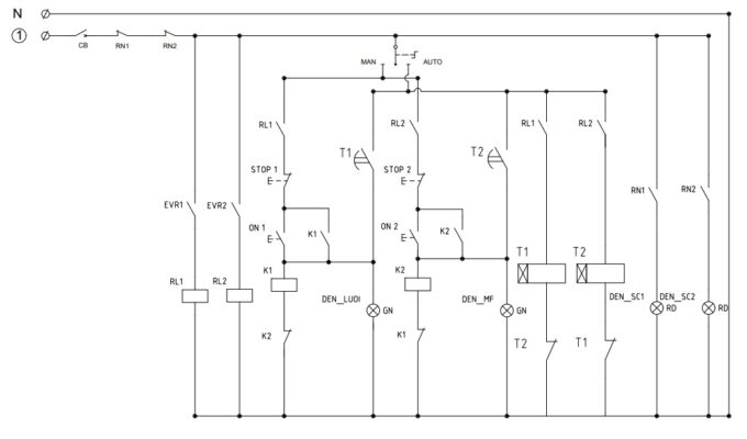
3 Phase Automatic Transfer Switch Ats Wiring Diagram Manual
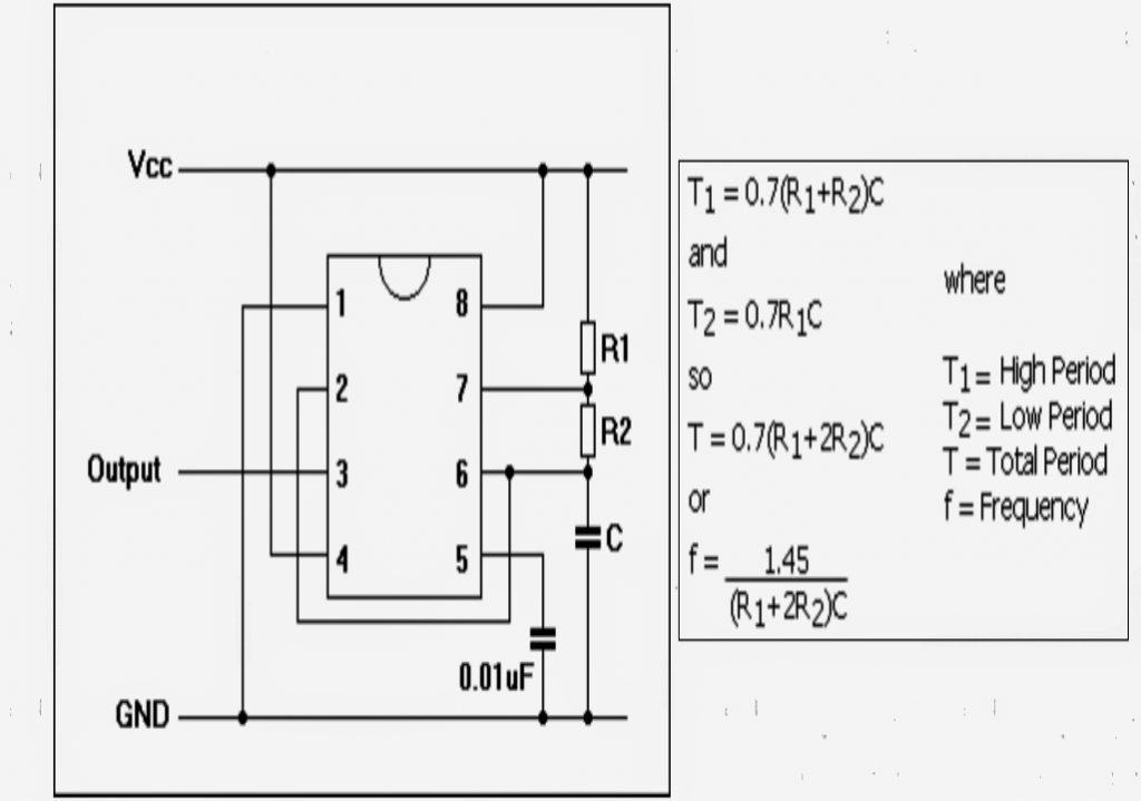
2 Simple Automatic Transfer Switch Ats Circuits Homemade Circuit Projects
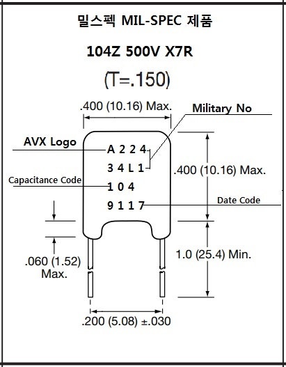
100nf500v 100nf 500v 0 1uf500v 0 1uf 500v Cr1201 0 1uf 120ohm Ac250v 네이버 블로그

Instructions On How To Install The Automatic Transfer Switch With Wiring Diagram Control Circuit The Dynamic Circuit With Sices Ats115 Ats Controller
Aggregate Control Unit Gencon Ii Pro Dsl Electronic Gmbh

Source Yuye Pc Class N Type Yes1 250n Ats Transfer Switch Automatic Transfer Switch Ats For Generator On M Alibaba Com
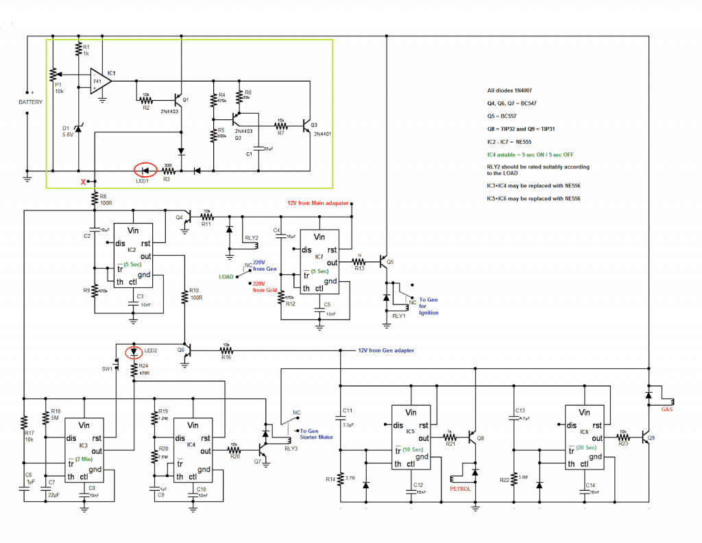
2 Simple Automatic Transfer Switch Ats Circuits Homemade Circuit Projects

Single Phase Ats Automatic Transfer Switch Wiring Diagram And Connection Etechnog